Using the driving support systems
Cruise control
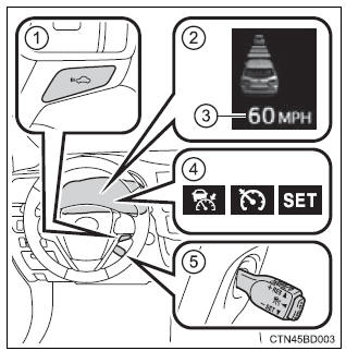
Summary of functions
Use the cruise control to maintain a set speed without depressing the accelerator pedal.
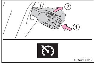
- Indicators
- Cruise control switch
>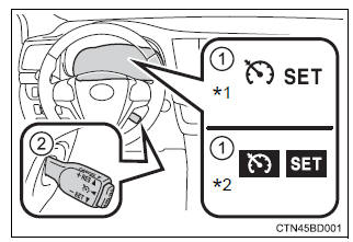
*1: vehicles with monochrome display *2: vehicles with color display
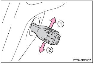
Setting the vehicle speed
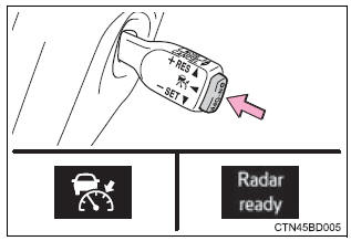
- Press the “on-off” button to activate the cruise control.
Cruise control indicator will come on*1 or will be displayed on the multi-information display*2.
Press the button again to deactivate the cruise control.
>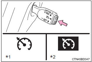
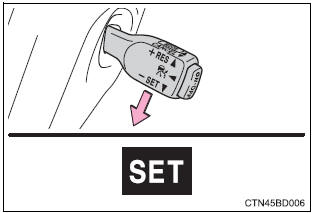
- Accelerate or decelerate the vehicle to the desired speed, and push the lever down to set the speed.
“Set” indicator will come on*1 or will be displayed on the multi-information display*2.
The vehicle speed at the moment the lever is released becomes the set speed.
>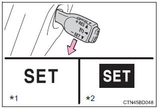
*1: Vehicles with monochrome display *2: vehicles with color display
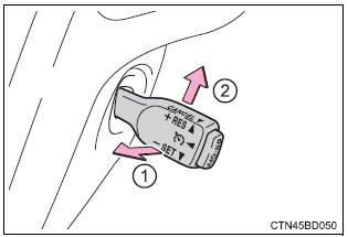
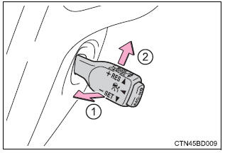
Adjusting the set speed
To change the set speed, operate the lever until the desired set speed is obtained.
- Increases the speed
- Decreases the speed
Fine adjustment: momentarily move the lever in the desired direction.
Large adjustment: hold the lever in the desired direction.
>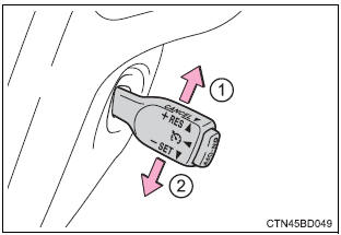
The set speed will be increased or decreased as follows: fine adjustment: by approximately 1 mph (1.6 Km/h) each time the lever is operated.
Large adjustment: the set speed can be increased or decreased continually until the lever is released.
Canceling and resuming the constant speed control
- Pulling the lever toward you cancels the constant speed control.
The speed setting is also canceled when the brakes are applied.
- Pushing the lever up resumes the constant speed control.
Resuming is available when the vehicle speed is more than approximately 25 mph (40 km/h).
>
Cruise control can be set when
- The shift lever is in the d or range 4 or higher of s has been selected.
- Vehicle speed is above approximately 25 mph (40 km/h).
Accelerating after setting the vehicle speed
- The vehicle can be accelerated normally. After acceleration, the set speed resumes.
- Even without canceling the cruise control, the set speed can be increased by first accelerating the vehicle to the desired speed and then pushing the lever down to set the new speed.
Automatic cruise control cancelation
Cruise control will stop maintaining the vehicle speed in any of the following situations.
- Actual vehicle speed falls more than approximately 10 mph (16 km/h) below the preset vehicle speed.
At this time, the memorized set speed is not retained.
- Actual vehicle speed is below approximately 25 mph (40 km/h).
- Enhanced vsc is activated.
- Vsc is activated.
If the warning message for the cruise control is shown on the multIInformation display
Press the “on-off” button once to deactivate the system, and then press the button again to reactivate the system.
If the cruise control speed cannot be set or if the cruise control cancels immediately after being activated, there may be a malfunction in the cruise control system. Have the vehicle inspected by your toyota dealer.
 Warning Warning
To avoid operating the cruise control by mistake
Switch the cruise control off using the "on-off" button when not in use. Situations unsuitable for cruise control
Do not use cruise control in any of the following situations. Doing so may result in loss of control and could cause an accident resulting in death or serious injury.
|
Dynamic radar cruise control
Summary of functions
Dynamic radar cruise control supplements conventional cruise control with a vehicle-to-vehicle distance control. In vehicle-to-vehicle distance control mode, the vehicle automatically accelerates or decelerates in order to maintain a set following distance from vehicles ahead.
- Vehicle-to-vehicle distance button
- display
- set speed
- indicators
- cruise control switch
>
Setting the vehicle speed (vehicle-to-vehicle distance control mode)
- Press the “on-off” button to activate the cruise control.
Radar cruise control indicator will be displayed.
Press the button again to deactivate the cruise control.
>
- Accelerate or decelerate the vehicle to the desired speed, and push the lever down to set the speed.
“Set” indicator will be displayed.
The vehicle speed at the moment the lever is released becomes the set speed.
>
Adjusting the set speed
To change the set speed, operate the lever until the desired set speed is displayed.
- Increases the speed
- Decreases the speed
Fine adjustment: momentarily move the lever in the desired direction.
Large adjustment: hold the lever in the desired direction.
>
In the vehicle-to-vehicle distance control mode, the set speed will be increased or decreased as follows:
- when the set speed is shown in "mph" fine adjustment: by approximately 1 mph (1.6 Km/h) each time the lever is operated large adjustment: by approximately 5 mph (8 km/h) for each 0.75 Seconds the lever is held
- when the set speed is shown in "km/h" fine adjustment: by approximately 0.6 Mph (1 km/h) each time the lever is operated large adjustment: by approximately 3.1 Mph (5 km/h) for each 0.75 Seconds the lever is held
In the constant speed control mode , The set speed will be increased or decreased as follows:
Fine adjustment: by approximately 1 mph (1.6 Km/h) each time the lever is operated large adjustment: the set speed can be increased or decreased continually until the lever is released.
Changing the vehicle-to-vehicle distance
Pressing the button changes the vehicle-to-vehicle distance as follows:
- long
- medium
- short
>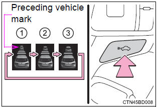
The vehicle-to-vehicle distance is set automatically to long mode when the engine switch is turned to ignition on mode.
If a vehicle is running ahead of you, the preceding vehicle mark will also be displayed.
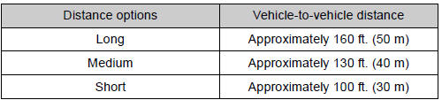
Vehicle-to-vehicle distance settings
Select a distance from the table below. Note that the distances shown correspond to a vehicle speed of 50 mph (80 km/h). Vehicle-to-vehicle distance increases/decreases in accordance with vehicle speed.
>
Canceling and resuming the speed control
- Pulling the lever toward you cancels the cruise control.
The speed setting is also canceled when the brakes are applied.
- Pushing the lever up resumes the cruise control and returns vehicle speed to the set speed.
Resuming is available when the vehicle speed is more than approximately 25 mph (40 km/h).
>
Driving in vehicle-to-vehicle distance control mode
This mode employs a radar sensor to detect the presence of vehicles up to approximately 400 ft. (120 M) ahead, determines the current vehicle-to-vehicle following distance, and operates to maintain a suitable following distance from the vehicle ahead.
Note that vehicle-to-vehicle distance will close in when traveling on long downhill slopes.
>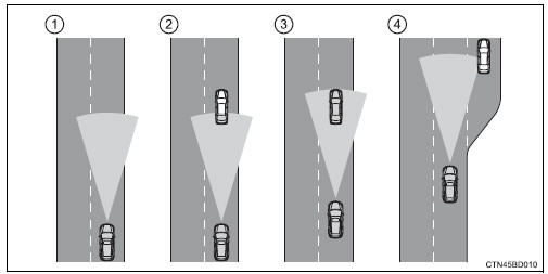
- Example of constant speed cruising when there are no vehicles ahead
The vehicle travels at the speed set by the driver. The desired vehicle-tovehicle distance can also be set by operating the vehicle-to-vehicle distance control.
- Example of deceleration cruising when the vehicle ahead is driving slower than the set speed
When a vehicle is detected running ahead of you, the system automatically decelerates your vehicle. When a greater reduction in vehicle speed is necessary, the system applies the brakes. A warning tone warns you when the system cannot decelerate sufficiently to prevent your vehicle from closing in on the vehicle ahead.
- Example of follow-up cruising when following a vehicle driving slower than the set speed
The system continues follow-up cruising while adjusting for changes in the speed of the vehicle ahead in order to maintain the vehicle-to-vehicle distance set by the driver.
- Example of acceleration when there are no longer any vehicles ahead driving slower than the set speed
The system accelerates until the set speed is reached. The system then returns to constant speed cruising.
Approach warning
When your vehicle is too close to a vehicle ahead, and sufficient automatic deceleration via the cruise control is not possible, the display will flash and the buzzer will sound to alert the driver. An example of this would be if another driver cuts in front of you while you are following a vehicle. Apply the brakes to ensure an appropriate vehicle-tovehicle distance.
Warnings may not occur when
In the following instances, there is a possibility that the warnings will not occur:
- when the speed of the vehicle ahead matches or exceeds your vehicle speed
- when the vehicle ahead is traveling at an extremely slow speed
- immediately after the cruise control speed was set
- at the instant the accelerator is applied
Selecting conventional constant speed control mode
Constant speed control mode differs from vehicle-to-vehicle distance control mode. When constant speed control mode is selected, your vehicle will maintain a set speed regardless of whether or not there are other vehicles in the lane ahead.
- Press the “on-off” button to activate the cruise control.
Press the button again to deactivate the cruise control.
- Switch to constant speed control mode.
(Push the lever forward and hold for approximately one second.)
>
Constant speed control mode indicator will be displayed.
When in constant speed control mode, to return to vehicle-to-vehicle distance control mode, push the lever forward again and hold for approximately 1 second.
After the desired speed has been set, it is not possible to return to vehicleto- vehicle distance control mode.
If the engine switch is turned off and then turned to ignition on mode again, the vehicle will automatically return to vehicle-to-vehicle distance control mode.
Adjusting the speed setting: Canceling and resuming the speed setting:
Dynamic radar cruise control can be set when
- The shift lever is in the d or range 4 or higher of s has been selected.
- Vehicle speed is above approximately 30 mph (50 km/h).
Accelerating after setting the vehicle speed
The vehicle can accelerate normally. After acceleration, the set speed resumes. However, during vehicle-to-vehicle distance control mode, the vehicle speed may decrease below the set speed in order to maintain the distance to the vehicle ahead.
Automatic cancelation of vehicle-to-vehicle distance control
Vehicle-to-vehicle distance control driving is automatically canceled in the following situations:
- actual vehicle speed falls below approximately 25 mph (40 km/h).
- Enhanced vsc is activated.
- Vsc is activated.
- The sensor cannot operate correctly because it is covered in some way.
- The windshield wipers are operating at high speed (when the wiper switch is set to the high speed wiper operation position).
If vehicle-to-vehicle distance control driving is automatically canceled for any other reason, there may be a malfunction in the system. Contact your toyota dealer.
Automatic cancelation of constant speed control
The cruise control will stop maintaining the vehicle speed in the following situations:
- actual vehicle speed is more than approximately 10 mph (16 km/h) below the set vehicle speed.
At this time, the memorized set speed is not retained.
- Vehicle speed falls below approximately 25 mph (40 km/h).
- Enhanced vsc is activated.
- Vsc is activated.
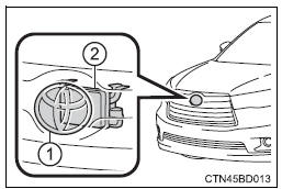
Radar sensor and grille cover
Always keep the sensor and grille cover clean to ensure that the vehicle-tovehicle distance control operates properly. (Some obstructions, such as snow, ice and plastic objects, cannot be detected by the obstruction sensor.) Dynamic radar cruise control is canceled if an obstruction is detected.
- Grille cover
- Radar sensor
>
Operation guide display
When the dynamic radar cruise control switch is operated, a guidance display is shown on the multi-information display for a few seconds as to how to operate the dynamic radar cruise control switch or distance switch.
Warning messages and buzzers for dynamic radar cruise control
Warning messages and buzzers are used to indicate a system malfunction or to inform the driver of the need for caution while driving.
Certification for dynamic radar cruise control
- For vehicles sold in the u.S.A.
Fcc id: hyqdnmwr007
This device complies with part 15 of the fcc rules. Operation is subject to the following two conditions : (1) this device may not cause harmful interference, and (2) this device must accept any interference received, including interference that may cause undesired operation.
Fcc warning
Changes or modifications not expressly approved by the party responsible for compliance could void the user's authority to operate the equipment.
Radiofrequency radiation exposure information: this equipment complies with fcc radiation exposure limits set forth for an uncontrolled environment.
This equipment should be installed and operated with minimum distance of 20 cm between the radiator (antenna) and your body.
This transmitter must not be co-located or operating in conjunction with any other antenna or transmitter.
- for vehicles sold in canada
Operation is subject to the following two conditions: (1) this device may not cause interference, and (2) this device must accept any interference, including interference that may cause undesired operation of the device.
 Warning Warning
Before using dynamic radar cruise control
Do not overly rely on vehicle-to-vehicle distance control. Be aware of the set speed. If automatic deceleration/acceleration is not appropriate, adjust the vehicle speed, as well as the distance between your vehicle and vehicles ahead by applying the brakes etc. Cautions regarding the driving assist systems
Observe the following precautions. Failure to do so may cause an accident resulting in death or serious injury.
To avoid inadvertent cruise control activation
Switch the cruise control off using the “on-off” button when not in use. Situations unsuitable for dynamic radar cruise control
Do not use dynamic radar cruise control in any of the following situations. Doing so may result in inappropriate speed control and could cause an accident resulting in death or serious injury.
When the sensor may not be correctly detecting the vehicle ahead
Apply the brakes as necessary when any of the following types of vehicles are in front of you. As the sensor may not be able to correctly detect these types of vehicles, the approach warning Will not be activated, and a fatal or serious accident may result.
Conditions under which the vehicle-to-vehicle distance control may not function correctly
Apply the brakes as necessary in the following conditions as the radar sensor may not be able to correctly detect vehicles ahead, and a fatal or serious accident may result:
H andling the radar sensor
Observe the following to ensure the cruise control system can function effectively. Otherwise, the system may not function correctly and could result in an accident.
|
Lda (lane departure alert)
Summary of function
While driving on a road that has lane markers, this system recognizes the lane markers using a camera as a sensor to alert the driver when the vehicle deviates from its lane.
If the system judges that the vehicle has deviated from its lane, it alerts the driver using a buzzer and indications on the multi-information display.
Camera sensor
>
Turning the lda system on
- Vehicles with monochrome display
>
- Vehicles with color display
>
Press the lda switch to activate the system.
The lda indicator and lane lines will come on.
Press the switch again to turn the lda system off.
The lda system will remain on or off even if the engine switch is turned to ignition on mode.
Operating conditions
- When the vehicle speed is approximately 32 mph (50 km/h) or more
- when the lane width is more than approximately 8.2 Ft. (2.5 M)
- when driving on a straight road or through a curve with a radius of more than approximately 328 ft. (100 M)
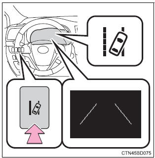
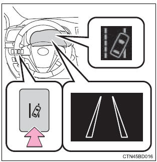
Indication on the multi-information display
- Vehicles with monochrome display
>
- Vehicles with color display
>
When the inside of both lane lines turn white: indicates that both right and left lane markers are recognized.
If the vehicle deviates from the lane, the lane line on the side the vehicle has deviated from will flash.
- Vehicles with monochrome display
>
- Vehicles with color display
>
When the inside of either lane line turns white: indicates that the lane marker on the white-marked side is recognized.
If the vehicle deviates from the side of a lane with recognized lane markers, the lane line will flash.
- Vehicles with monochrome display
>
When both lane lines are shown in fine lines:
Indicates that no lane markers are recognized or the lda system is temporarily canceled.
- Vehicles with color display
>
When the inside of both lane lines are black:
Indicates that no lane markers are recognized or the lda system is temporarily canceled.
Temporary cancelation of the lda system functions
If any of the following occurs, the lda system functions will be temporarily canceled. The functions will resume after the necessary operating conditions have returned.
- The turn signal lever is operated.
- The vehicle speed deviates from the operating range of the lda system functions.
- When the lane lines cannot be recognized while driving.
- When the lane departure warning function is activated.
The lane departure warning function will not operate again for a several seconds after it has been activated, even if the vehicle leaves the lane again.
The lane departure warning
Depending on the audio system sound level or air conditioning fan noise while the audio system or air conditioning system is in use, it may be difficult to hear the warning sound.
After the vehicle has been parked in the sun
The lda system may not be available and a warning message Will be displayed for a while after driving has started. When the temperature in the cabin decreases and the temperature around the camera sensor Becomes suitable for its operation, the functions will begin to operate.
If there are lane markers on only one side of the vehicle
The lane departure warning will not operate for the side on which lane markers could not be recognized.
Conditions in which the function may not operate correctly
In the following situations, the camera sensor may be unable to recognize lane markers causing the lane departure warning function to operate incorrectly.
However, this does not indicate a malfunction.
- When driving through an area with no lane markers, such as a tollbooth, a crossing or before a ticket checkpoint
- when driving on a sharp curve
- when lane markers are extremely narrow or extremely wide
- when the vehicle leans to one side an unusual amount due to a heavy load or improper tire inflation pressure
- when the following distance between your vehicle and the vehicle ahead is extremely short
- when the lane markers are yellow (these may be more difficult for the system to recognize compared to white markers.)
- When the lane markers are broken, botts' dots (raised pavement markers) or stones
- when the lane markers are on a curb etc.
- When lane markers are obscured or partially obscured by sand, dirt, etc.
- When there are shadows on the road running parallel with lane markers, or if a shadow covers the lane markers
- when driving on a particularly bright road surface, such as concrete
- when driving on a road surface that is bright due to reflected light
- when driving in a location where the light level changes rapidly, such as the entrance to or exit from a tunnel
- when sunlight or the headlights of oncoming vehicles are shining directly into the camera lens
- when driving on roads that are branching or merging
- when driving on a road surface that is wet due to rain, previous rainfall, standing water, etc.
- When the vehicle experiences strong up-and-down motion such as when driving on an extremely rough road or on a seam in the pavement
- when headlight brightness at nighttime is reduced due to dirt on the lenses, or when the headlights are misaligned
- when driving on winding roads or roads that are uneven
- when driving on rough or unpaved roads
When changing the tires
Depending on the tires used, sufficient performance may not be maintainable.
Warning messages for the lda system
Warning messages are used to indicate a system malfunction or to inform the driver of the need for caution while driving.
 Warning Warning
Before using the lda system
Do not rely solely on the lda system. The lda system does not drive the vehicle automatically, nor does it reduce the amount of care you need to take. As such, the driver must always assume full responsibility for understanding his/her surroundings, for operating the steering wheel to correct the driving line, and for driving safely. Inappropriate or negligent driving could lead to an accident. To avoid operating the lda by mistake
Switch the lda system off using the lda switch when not in use. Situations unsuitable for lda system
Do not use the lda system in any of the following situations. Otherwise, the system may not function correctly and could result in an accident.
|
 Notice Notice
To prevent damage to or incorrect operation of the lda system
Camera sensor
Observe the following to ensure that the lda system functions correctly.
>
|
Rear view monitor system
Refer to the "navigation and multimedia system owner's manual".
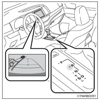
The rear view monitor system assists the driver by displaying guide lines and an image of the view behind the vehicle while backing up, for example while parking. The screen illustrations used in this text are intended as examples, and may differ from the image that is actually displayed on the screen. |
The rear view image is displayed when the shift position is in r and the engine switch is in “on” position.
The rear view monitor system will be deactivated when the shift lever is in any position other than r.
>
Using the rear view monitor system
Screen description
The rear view monitor system screen will be displayed if the shift lever is shifted to r while the engine switch is in “on” position.
>
- Vehicle width guide lines the line indicates a guide path when the vehicle is being backed straight up.The displayed width is wider than the actual vehicle width.
- Vehicle center guide lines these lines indicate the estimated vehicle center on the ground.
- Distance guide line the line shows points approximately 1.5 Ft. (0.5 M) (red) from the center of the edge of the bumper.
- Distance guide line the line shows distance behind the vehicle, a point approximately 3 ft.
(1 M) (blue) from the edge of the bumper.
Rear view monitor system precautions
Area displayed on screen
The rear view monitor system displays an image of the view from the bumper of the rear area of the vehicle.
To adjust the image on the rear view monitor system screen.
>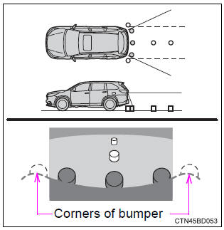
- The area displayed on the screen may vary according to vehicle orientation conditions.
- Objects which are close to either corner of the bumper or under the bumper cannot be seen on the screen.
- The camera uses a special lens. The distance of the image that appears on the screen differs from the actual distance.
- Items which are located higher than the camera may not be displayed by the monitor.
Rear view monitor system camera
The camera for the rear view monitor system is located above the license plate.
>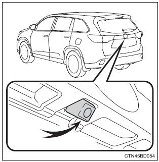
- Using the camera
If the camera lens becomes dirty, it cannot transmit a clear image. If water droplets, snow or mud adhere to the lens, rinse it with water and wipe with a soft cloth. If the lens is extremely dirty, wash it with a mild cleanser and rinse.
Differences between the screen and the actual road
The distance guide lines and the vehicle width guide lines may not actually be parallel with the dividing lines of the parking space, even when they appear to be so. Be sure to check visually.
The distances between the vehicle width guide lines and the left and right dividing lines of the parking space may not be equal, even when they appear to be so. Be sure to check visually.
The distance guide lines give a distance guide for flat road surfaces.
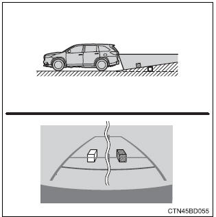
In any of the following situations, there is a margin of error between the fixed guide lines on the screen and the actual distance/ course on the road.
- When the ground behind the vehicle slopes up sharply
The distance guide lines will appear to be closer to the vehicle than the actual distance.
Because of this, objects will appear to be farther away than they actually are. In the same way, there will be a margin of error between the guidelines and the actual distance/course on the road.
>
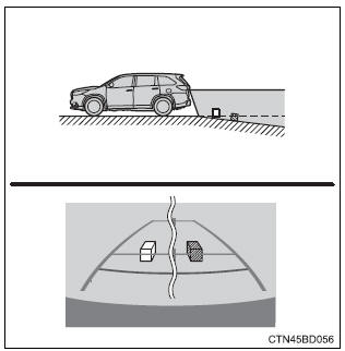
- When the ground behind the vehicle slopes down sharply
The distance guide lines will appear to be further from the vehicle than the actual distance.
Because of this, objects will appear to be closer than they actually are. In the same way, there will be a margin of error between the guidelines and the actual distance/course on the road.
>
- When any part of the vehicle sags
When any part of the vehicle sags due to the number of passengers or the distribution of the load, there is a margin of error between the fixed guide lines on the screen and the actual distance/course on the road.
>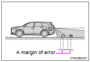
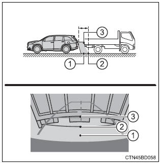
When approaching three-dimensional objects
The distance guide lines are displayed according to flat surfaced objects (such as the road). It is not possible to determine the position of three-dimensional objects (such as vehicles) using the distance guide lines. When approaching a three-dimensional object that extends outward (such as the flatbed of a truck), be careful of the following.
- Distance guidelines
Visually check the surroundings and the area behind the vehicle.
On the screen, it appears that a truck is parked at point 2. However, in reality if you back up to point 1, you will hit the truck. On the screen, it appears that 1 is closest and 3 is furthest away. However, in reality, the distance to 1 and 3 is the same, and 2 is farther than 1 and 3.
>
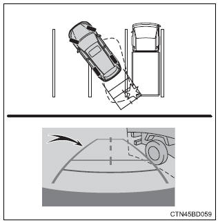
Vehicle width guide lines
Visually check the surroundings and the area behind the vehicle. In the case shown below, the truck appears to be outside of the vehicle width guide lines and the vehicle does not look as if it hits the truck. However, the rear body of the truck may actually cross over the vehicle width guide lines. In reality if you back up as guided by the vehicle width guide lines, the vehicle may hit the truck.
Vehicle width guide lines
>
Things you should know
If you notice any symptoms
If you notice any of the following symptoms, refer to the likely cause and the solution, and re-check.
If the symptom is not resolved by the solution, have the vehicle inspected by your toyota dealer.
|
>Likely cause
|
>Solution
|
| The image is difficult to see
|
|
|
If this happens due to these causes, it does not indicate a malfunction.
Back up while visually checking the vehicle’s surroundings. (Use the monitor again once conditions have been improved.) To adjust the image on the rear view monitor system screen. |
| The image is blurry
|
|
| Dirt or foreign matter (such as water droplets, snow, mud etc.) Is adhering to the camera. | Rinse the camera lens with water and wipe it clean with a soft cloth.
Wash with a mild soap if the dirt is stubborn. |
| The image is out of alignment
|
|
| The camera or surrounding area has received a strong impact. | Have the vehicle inspected by your toyota dealer. |
| The fixed guide lines are very far out of alignment
|
|
|
If this happens due to these causes, it does not indicate a malfunction.
Back up while visually checking the vehicle's surroundings. |
| The camera position is out of alignment. | Have the vehicle inspected by your toyota dealer. |
 Warning Warning
When using the rear view monitor system
The rear view monitor system is a supplemental device intended to assist the driver when backing up. When backing up, be sure to check visually behind and all around the vehicle before proceeding. Observe the following precautions to avoid an accident that could result in death or serious injuries.
|
 Notice Notice
How to use the camera
|
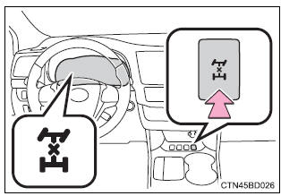
All-wheel drive lock switch
All-wheel drive lock mode can be used when a large amount of drive power needs to be applied to all the wheels, such as when the vehicle gets stuck in mud and you need to free it.
Press the switch.
The torque of the engine is distributed to the rear wheels to the maximum extent possible in accordance with driving conditions.
Pressing the switch again cancels all-wheel drive lock mode and returns the dynamic torque control awd system to normal mode.
>
All-wheel drive lock mode can be operated when
- Vehicles without a smart key system the engine switch is in the "on" position.
- vehicles with a smart key system the engine switch is in ignition on mode.
All-wheel drive lock mode
- All-wheel drive lock mode is canceled when the brakes are applied to ensure the abs and vsc systems operate effectively.
- All-wheel drive lock mode is canceled when the vehicle speed exceeds 25 mph (40 km/h).
Driving assist systems
To help enhance driving safety and performance, the following systems operate automatically in response to various driving situations. Be aware, however, that these systems are supplementary and should not be relied upon too heavily when operating the vehicle.
Abs (anti-lock brake system)
Helps to prevent wheel lock when the brakes are applied suddenly, or if the brakes are applied while driving on a slippery road surface
Brake assist
Generates an increased level of braking force after the brake pedal is depressed when the system detects a panic stop situation
Vsc (vehicle stability control)
Helps the driver to control skidding when swerving suddenly or turning on slippery road surfaces
Enhanced vsc (enhanced vehicle stability control)
Provides cooperative control of the abs, trac, vsc and eps.
Helps to maintain directional stability when swerving on slippery road surfaces by controlling steering performance.
Trac (traction control)
Helps to maintain drive power and prevent the drive wheels from spinning when starting the vehicle or accelerating on slippery roads
Hill-start assist control
Prevents the vehicle from rolling backward when starting on an incline or slippery slope
Downhill assist control system (awd models)
Dynamic torque control awd system (awd models)
Automatically switches from front-wheel drive to all-wheel drive (awd) according to the driving conditions, helping to ensure reliable handling and stability. Examples of conditions where the system will switch to awd are when cornering, going uphill, starting off or accelerating, and when the road surface is slippery due to snow, rain, etc.
Eps (electric power steering)
Employs an electric motor to reduce the amount of effort needed to turn the steering wheel
Pcs (pre-collision system) (if equipped)
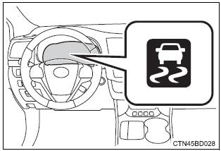
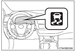
When the trac/vsc systems are operating
The slip indicator light will flash while the trac/vsc systems are operating.
>
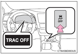
Disabling the trac system
If the vehicle gets stuck in mud, dirt or snow, the trac system may reduce power from the engine to the wheels. Pressing  to turn the
system off may make it easier for you to rock the vehicle in order to free it.
to turn the
system off may make it easier for you to rock the vehicle in order to free it.
To turn the trac system off, quickly press and release  .
.
The “trac off” will be shown on the multi-information display. Press  again to turn the system back
on.
again to turn the system back
on.
>
Turning off both trac and vsc systems
To turn the trac and vsc systems off, press and hold for more than 3
seconds while the vehicle is stopped.
The vsc off indicator light will come on and the “trac off” will be shown on the multi-information display.* Press again to turn the systems
back on.
*: On vehicles with pre-collision system, pre-collision brake assist and precollision braking will also be disabled. The pre-collision system warning light will come on and the message will be shown on the multi-information display.
When the message is displayed on the multi-information display showing that trac has been disabled even if
switch has not been
pressed
Trac, hill-start assist control and downhill assist control cannot be operated.
Contact your toyota dealer.
Sounds and vibrations caused by the abs, brake assist, trac, vsc and hill-start assist control systems
- Sound may be heard from the engine compartment when the brake pedal is depressed repeatedly, when the engine is started or just after the vehicle begins to move. This sound does not indicate that a malfunction has occurred in any of these systems.
- Any of the following conditions may occur when the above systems are operating. None of these indicates that a malfunction has occurred.
- Vibrations may be felt through the vehicle body and steering.
- A motor sound may be heard after the vehicle comes to a stop.
- The brake pedal may pulsate slightly after the abs is activated.
- The brake pedal may move down slightly after the abs is activated.
Eps operation sound
When the steering wheel is operated, a motor sound (whirring sound) may be heard. This does not indicate a malfunction.
Automatic reactivation of trac and vsc systems
After turning the trac and vsc systems off, the systems will be automatically re-enabled in the following situations:
- vehicles without a smart key system: when the engine switch is turned to the "lock" position vehicles with a smart key system: when the engine switch is turned off
- if only the trac system is turned off, the trac will turn on when vehicle speed increases if both the trac and vsc systems are turned off, automatic re-enabling will not occur when vehicle speed increases.
Reduced effectiveness of the eps system
The effectiveness of the eps system is reduced to prevent the system from overheating when there is frequent steering input over an extended period of time. The steering wheel may feel heavy as a result. Should this occur, refrain from excessive steering input or stop the vehicle and turn the engine off. The eps system should return to normal within 10 minutes.
Operating conditions of hill-start assist control
When the following four conditions are met, the hill-start assist control will operate:
- the shift lever is in a position other than p or n (when starting off forward/ backward on an upward incline).
- The vehicle is stopped.
- The accelerator pedal is not depressed.
- The parking brake is not engaged.
Automatic system cancelation of hill-start assist control
The hill-start assist control will turn off in any of the following situations:
- the shift lever is moved to p or n.
- The accelerator pedal is depressed.
- The parking brake is engaged.
- Approximately 2 seconds elapse after the brake pedal is released.
 Warning Warning
The abs does not operate effectively when
Stopping distance when the abs is operating may exceed that of normal conditions
The abs is not designed to shorten the vehicle's stopping distance. Always maintain a safe distance from the vehicle in front of you, especially in the following situations:
Trac may not operate effectively when
Directional control and power may not be achievable while driving on slippery road surfaces, even if the trac system is operating. Drive the vehicle carefully in conditions where stability and power may be lost. Hill- start assist control
When the vsc is activated
The slip indicator light flashes. Always drive carefully. Reckless driving may cause an accident. Exercise particular care when the indicator light flashes. When the trac/vsc systems are turned off
Be especially careful and drive at a speed appropriate to the road conditions. As these are the systems to help ensure vehicle stability and driving force, do not turn the trac/vsc systems off unless necessary. Replacing tires
Make sure that all tires are of the specified size, brand, tread pattern and total load capacity. In addition, make sure that the tires are inflated to the recommended tire inflation pressure level. The abs, trac and vsc systems will not function correctly if different tires are installed on the vehicle. Contact your toyota dealer for further information when replacing tires or wheels. Handling of tires and the suspension
Using tires with any kind of problem or modifying the suspension will affect the driving assist systems, and may cause a system to malfunction. |
Downhill assist control system
With the downhill assist control system, the vehicle is able to descend a steep hill, maintaining a constant low speed of about 3 mph (5 km/h) without brake pedal operation.
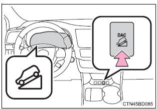
Activating the downhill assist control system
Activating the downhill assist control system press the “dac” switch.
The downhill assist control system indicator will come on to indicate that the downhill assist control system is activated.
Pressing the switch again turns the system off.
>
While the downhill assist control system is operating
The slip indicator will flash to indicate that the downhill assist control system is operating, and the stop lights and high mounted stoplight will turn on.
>
Conditions in which the downhill assist control system does not operate
- In the following situations, the downhill assist control system indicator flashes and the downhill assist control system does not operate or will stop operating:
- The shift lever is not in 1 range of s mode or r.
- The vehicle speed is higher than 15 mph (25 km/h).
- If the accelerator or brake pedal is depressed, the downhill assist control system will stop operating with the downhill assist control system indicator still on.
If the “dac” switch is turned off during operation of the downhill assist control system
The downhill assist control system gradually ceases operation. The downhill assist control system indicator will flash during the canceling operation, and then go off when the system is fully off.
Downhill assist control system operation sound
- ?A sound may be heard from the engine compartment during operation of the downhill assist control system. This sound does not indicate a malfunction.
- If the accelerator or brake pedal is depressed during operation of the downhill assist control system, a sound caused by the release of system operation may be heard, or you may feel the brake pedal push-back. This does not indicate a malfunction.
When the downhill assist control system operates continuously
The brake actuator may overheat. In that case, the downhill assist control system will stop operating, a buzzer will sound and the downhill assist control system indicator will start flashing. Refrain from using the system until the downhill assist control system indicator stays on. (There is no problem with continuing to drive normally.)
If the slip indicator comes on
It may indicate a malfunction in the system. Contact your toyota dealer.
 Warning Warning
Conditions which may affect the downhill assist control system operation
|
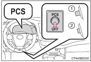
Pcs (pre-collision system)
When the radar sensor detects that a frontal collision is highly likely or even unavoidable, safety systems such as the brakes and seat belts are automatically engaged to lessen impact as well as vehicle damage.
The pre-collision system can be turned on and off as necessary by operating the switch.
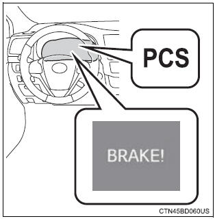
Pre-collision warning
When a high possibility of a frontal collision is detected, the pre-collision system warning light flashes, a buzzer sounds and a message is shown on the multi-information display to urge the driver to take evasive action.
>
Pre-collision brake assist
When there is a high possibility of a frontal collision, the system applies greater braking force in relation to how strongly the brake pedal is depressed.
The system may not warn the driver using a warning light, warning display and buzzer when the system detects and judges braking operations.
Pre-collision braking
When there is a high possibility of a frontal collision, the system warns the driver using a warning light, warning display and buzzer.
If the system determines that a collision is unavoidable, the brakes are automatically applied to reduce the collision speed.
Disabling pre-collision system
- Enabled
- Disabled
The pre-collision system warning light comes on when pre-collision system is disabled.
>
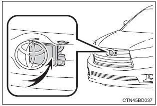
Radar sensor
The radar sensor detects vehicles or other obstacles on or near the road ahead and determines whether a collision is imminent based on the position, speed, and heading of the obstacles.
>
The pre-collision system is operational when
The pcs off switch is not pressed and the following conditions are met:
- Pre-collision warning:
- Vehicle speed is greater than about 10 mph (15 km/h).
- The speed at which your vehicle is approaching the obstacle or the vehicle running ahead of you is greater than about 10 mph (15 km/h).
- Pre-collision brake assist:
- The vsc off switch is not pressed.
- Vehicle speed is greater than about 19 mph (30 km/h).
- The speed at which your vehicle is approaching the obstacle or the vehicle running ahead of you is greater than about 19 mph (30 km/h).
- The brake pedal is depressed.
- Pre-collision braking:
- The vsc off switch is not pressed.
- Vehicle speed is greater than about 10 mph (15 km/h).
- The speed at which your vehicle is approaching the obstacle or the vehicle running ahead of you is greater than about 10 mph (15 km/h).
Conditions that may trigger the system even if there is no danger of a collision
- When there is an object by the roadside at the entrance to a curve
- when passing an oncoming vehicle on a curve
- when driving over a narrow iron bridge
- when there is a metal object on the road surface
- when driving on an uneven road surface
- when passing an oncoming vehicle on a left-turn
- when your vehicle rapidly closes on the vehicle in front
- when a grade separation/interchange, sign, billboard, or other structure appears to be directly in the vehicle's line of travel
- when there is a metal plate in the road in front of the vehicle on a downhill slope
- when climbing a steep hill causes an overhead billboard or other metallic structure to appear directly in the vehicle's line of travel
- when driving under an overpass
- when an extreme change in vehicle height occurs
- when passing through certain toll gates
- when passing through a tunnel
- when the radar sensor moves off position due to its surrounding area being subjected to a strong impact
When the system is activated in the situations described above, there is also a possibility that the brakes will be applied with a force greater than normal.
Obstacles not detected
The sensor cannot detect plastic obstacles such as traffic cones. There may also be occasions when the sensor cannot detect pedestrians, animals, bicycles, motorcycles, trees, or snowdrifts.
Situations in which the pre-collision system does not function properly
The system may not function effectively in situations such as the following:
- on roads with sharp bends or uneven surfaces
- if a vehicle suddenly moves in front of your vehicle, such as at an intersection
- if a vehicle suddenly cuts in front of your vehicle, such as when overtaking
- in inclement weather such as heavy rain, fog, snow or sand storms
- if the vehicle is skidding when vsc is not operating
- when an extreme change in vehicle height occurs
- when only part of your vehicle's front end collides with, or contacts, a vehicle or object in a frontal collision
- when the radar sensor moves off position due to its surrounding area being subjected to a strong impact
Automatic cancelation of the pre-collision system
When a malfunction occurs due to sensor contamination, etc. That results in the sensors being unable to detect obstacles, the pre-collision system will be automatically disabled. In this case, the system will not activate even if there is a collision possibility.
When there is a malfunction in the system
The pre-collision system warning light will flash and warning messages will be displayed.
Certification for the pre-collision system
- For vehicles sold in the u.S.A.
Fcc id : hyqdnmwr007
This device complies with part 15 of the fcc rules. Operation is subject to the following two conditions :(1) this device may not cause harmful interference, and (2) this device must accept any interference received, including interference that may cause undesired operation.
Fcc warning
Changes or modifications not expressly approved by the party responsible for compliance could void the user's authority to operate the equipment.
Radiofrequency radiation exposure information: this equipment complies with fcc radiation exposure limits set forth for an uncontrolled environment.
This equipment should be installed and operated with minimum distance of 20 cm between the radiator (antenna) and your body.
This transmitter must not be co-located or operating in conjunction with any other antenna or transmitter.
- For vehicles sold in canada
Operation is subject to the following two conditions: (1) this device may not cause interference, and (2) this device must accept any interference, including interference that may cause undesired operation of the device.
 Warning Warning
Limitations of the pre-collision system
Do not overly rely on the pre-collision system. Always drive safely, taking care to observe your surroundings and checking for any obstacles or other road hazards. Failure to do so may cause an accident resulting in death or serious injury. When the sensor may not be correctly detecting the vehicle ahead
Apply the brakes as necessary in any of the following situations:
H andling the radar sensor
Observe the following to ensure the pre-collision system can function effectively. Otherwise, the system may not function correctly and could result in an accident.
Cautions regarding the assist contents of the system
By means of alarms and brake control, the pre-collision system is intended to assist the driver in avoiding collisions through the process of lookjudge- act. There are limits to the degree of assistance the system can provide, so please keep in mind the following important points.
|
Bsm (blind spot monitor)
Summary of the blind spot monitor
The blind spot monitor is a system that has 2 functions;
- the blind spot monitor function assists the driver in making the decision when changing lanes
- the rear cross traffic alert function assists the driver when backing up
These functions use same sensors.
>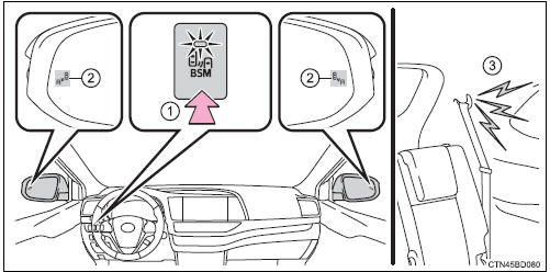
- Bsm main switch
Pressing the switch turns the system on or off. When the switch is set to on, the switch’s indicator illuminates and the buzzer sounds. Common switch for blind spot monitor function and rear cross traffic alert function.
- Outside rear view mirror indicators
Blind spot monitor function: when a vehicle is detected in the blind spot, the outside rear view mirror indicator comes on while the turn signal lever is not operated and the outside rear view mirror indicator flashes while the turn signal lever is operated.
Rear cross traffic alert function: when a vehicle approaching from the right or left rear of the vehicle is detected, the outside rear view mirror indicators flash.
- Rear cross traffic alert buzzer (rear cross traffic alert function only)
When a vehicle approaching from the right or left rear of the vehicle is detected, a buzzer sounds from behind the left-hand third seat.
The outside rear view mirror indicators visibility
When under strong sunlight, the outside rear view mirror indicator may be difficult to see.
Rear cross traffic alert buzzer hearing
Rear cross traffic alert function may be difficult to hear over loud noises such as high audio volume.
When there is a malfunction in the blind spot monitor
If a system malfunction is detected due to any of the following reasons, warning message will be displayed:
- There is a malfunction with the sensors
- the sensors have become dirty
- the outside temperature is extremely high or low
- the sensor voltage has become abnormal
Certification for the blind spot monitor
- For vehicles sold in the u.S.A.
Fcc id: oaysrr2a
This device complies with part 15 of the fcc rules. Operation is subject to the following two conditions:
- this device may not cause harmful interference, and
- this device must accept any interference received, including interference that may cause undesired operation.
Fcc warning
Changes or modifications not expressly approved by the party responsible for compliance could void the user's authority to operate the equipment.
- for vehicles sold in canada
Applicable law: canada 310
This device complies with industry canada licence-exempt rss standard(s).
Operation is subject to the following two conditions: (1) this device may not cause interference, and (2) this device must accept any interference, including interference that may cause undesired operation of the device.
Frequency bands: 24.05-24.25 Ghz output power: less than 20 milliwatts
 Warning Warning
Handling the radar sensor
One blind spot monitor sensor is installed inside the left and right side of the vehicle rear bumper respectively. Observe the following to ensure the blind spot monitor can function correctly.
>
|
The blind spot monitor function
The blind spot monitor function uses radar sensors to detect vehicles that are traveling in an adjacent lane in the area that is not reflected in the outside rear view mirror (the blind spot), and advises the driver of the vehicles existence via the outside rear view mirror indicator.
The blind spot monitor function detection areas
The areas that vehicles can be detected in are outlined below.
The range of the detection area extends to:
- approximately 11.5 Ft. (3.5 M) from the side of the vehicle the first 1.6 Ft. (0.5 M) from the side of the vehicle is not in the detection area
- approximately 9.8 Ft. (3 M) from the rear bumper
- approximately 3.3 Ft. (1 M) forward of the rear bumper
>
 Warning Warning
Cautions regarding the use of the system
The driver is solely responsible for safe driving. Always drive safely, taking care to observe your surroundings. The blind spot monitor function is a supplementary function which alerts the driver that a vehicle is present in the blind spot. Do not overly rely on the blind spot monitor function. The function cannot judge if it is safe to change lanes, therefore over reliance could cause an accident resulting in death or serious injury. According to conditions, the system may not function correctly. Therefore the driver’s own visual confirmation of safety is necessary. |
The blind spot monitor function is operational when
- The bsm main switch is set to on
- vehicle speed is greater than approximately 10 mph (16 km/h).
The blind spot monitor function will detect a vehicle when
- A vehicle in an adjacent lane overtakes your vehicle.
- Another vehicle enters the detection area when it changes lanes.
Conditions under which the blind spot monitor function will not detect a vehicle
The blind spot monitor function is not designed to detect the following types of vehicles and/or objects:
- small motorcycles, bicycles, pedestrians etc.*
- Vehicles traveling in the opposite direction
- guardrails, walls, signs, parked vehicles and similar stationary objects*
- following vehicles that are in the same lane*
- vehicles driving 2 lanes across from your vehicle*
*: depending on conditions, detection of a vehicle and/or object may occur.
Conditions under which the blind spot monitor function may not function correctly
- The blind spot monitor function may not detect vehicles correctly in the following conditions:
- During bad weather such as heavy rain, fog, snow etc.
- When ice or mud etc. Is attached to the rear bumper
- When driving on a road surface that is wet due to rain, standing water etc.
- When there is a significant difference in speed between your vehicle and the vehicle that enters the detection area
- When a vehicle is in the detection area from a stop and remains in the detection area as your vehicle accelerates
- When driving up or down consecutive steep inclines, such as hills, a dip in the road etc.
- When multiple vehicles approach with only a small gap between each vehicle
- When vehicle lanes are wide, and the vehicle in the next lane is too far away from your vehicle
- When the vehicle that enters the detection area is traveling at about the same speed as your vehicle
- When there is a significant difference in height between your vehicle and the vehicle that enters the detection area
- Directly after the bsm main switch is set to on
- When towing a trailer
- Instances of the blind spot monitor function unnecessarily detecting a vehicle and/or object may increase under the following conditions:
- When there is only a short distance between your vehicle and a guardrail, wall etc.
- When there is only a short distance between your vehicle and a following vehicle
- When vehicle lanes are narrow and a vehicle driving 2 lanes across from your vehicle enters the detection area
- When items such as a bicycle carrier are installed on the rear of the vehicle
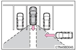
The rear cross traffic alert function
The rear cross traffic alert functions when your vehicle is in reverse.
It can detect other vehicles approaching from the right or left rear of the vehicle. It uses radar sensors to alert the driver of the other vehicle’s existence through flashing the outside rear view mirror indicators and sounding a buzzer.
>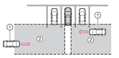
- Pproaching vehicles
- Detection areas
 Warning Warning
Cautions regarding the use of the system
The driver is solely responsible for safe driving. Always drive safely, taking care to observe your surroundings. The rear cross traffic alert function is only an assist and is not a replacement for careful driving. Driver must be careful when backing up, even when using rear cross traffic alert function. The driver’s own visual confirmation of behind you and your vehicle is necessary and be sure there are no pedestrians, other vehicles etc. Before backing up. Failure to do so could cause death or serious injury. According to conditions, the system may not function correctly. Therefore the driver’s own visual confirmation of safety is necessary. |
The rear cross traffic alert function detection areas
The areas that vehicles can be detected in are outlined below.
>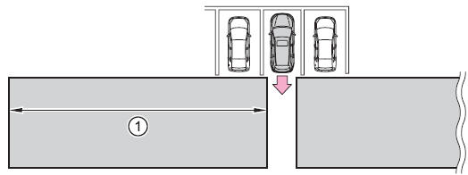
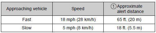
To give the driver a more consistent time to react, the buzzer can alert for faster vehicles from farther away.
Example:
>
The rear cross traffic alert function is operational when
- The bsm main switch is set to on.
- The shift lever is in r.
- Vehicle speed is less than approximately 5 mph (8 km/h).
- Approaching vehicle speed is between approximately 5 mph (8 km/h) and 18 mph (28 km/h).
Conditions under which the rear cross traffic alert function will not detect a vehicle
The rear cross traffic alert function is not designed to detect the following types of vehicles and/or objects.
- Small motorcycles, bicycles, pedestrians etc.*
- Vehicles approaching from directly behind
- guardrails, walls, signs, parked vehicles and similar stationary objects*
- vehicles moving away from your vehicle
- vehicles approaching from the parking spaces next to your vehicle*
- vehicles backing up in the parking space next to your vehicle*
*: depending on conditions, detection of a vehicle and/or object may occur.
Conditions under which the rear cross traffic alert function may not function correctly
The rear cross traffic alert function may not detect vehicles correctly in the following conditions:
- when ice or mud etc. Is attached to the rear bumper
- during bad weather such as heavy rain, fog, snow etc.
- When multiple vehicles approach continuously
- shallow angle parking
- when a vehicle is approaching at high speed
- when parking on a steep incline, such as hills, a dip in the road etc.
- Directly after the bsm main switch is set to on
- directly after the engine is started with the bsm main switch on
- when towing a trailer
- vehicles that the sensors cannot detect because of obstacles
>
Download Manual